Miniaturized pFI Instrument.
1.4.3.


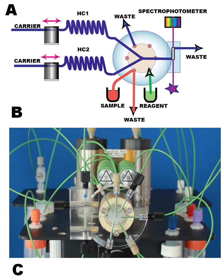
The programmable mini pFI instrument is designed by upsizing the lab-on- valve platform as a centerpiece. The sequence of the principle components of the flow path is different from the traditional design, since the reactors (holding coils HS1 and HC2) are situated upstream from the injection point (A). This design successfully used for Sequential Injection (Chapter 2) allows assay optimization be carried out by flow programming, rather than by physical reconfiguration of flow path, as necessitated when reactors are situated downstream from injection valve.
The instrument (B), miniSIA-2, manufactured by Global FIA is equipped with two miliGAT pumps, two thermostated holding coils, lab-on-valve module, externally mounted flow cell, fiber optic cables and for spectrophotometric detection a tungsten light source and the Ocean Optics Spectrophotometer. The pFI instrument operates on programmable flow, uses DI water as carrier and while sample and reagent volumes are in the range of 10 to 100 microliters per assay. The instrument generates about 1/10 of waste compared to cFI because the pumps are idle during sup flow incubation period and when samples are not being analyzed.
The lab-on- valve module (C) comprises the confluence point, flow trough sample injection port reagent ports and an externally mounted flow cell. The flow cell, shown here with 1 cm long optical path, can be extended up to 20 cm or replaced by flow cell designed for fluorescence or for chemiluminiscence. The movie clip (C) visualizes sample injection of a blue dye, followed by reagent addition (colorless acid) and following transport of dye, converted into acid form (yellow) into and trough the flowcell.